
myWerkzeug.de › CNC.myWerkzeug.de › Templates › myWerkzeug.de
CNC template · myWerkzeug.de
12 V power supply from the Electronics House
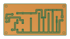
The board for the power supply room: fuse, bridge rectifier, reservoir capacitor and 7812 regulator turn a 12 V AC plug-in adapter into smooth 12 V for the other boards, up to about 300 mA. No 230 V on the board.
- Size
- 102 × 56 mm, 1.6 mm thick
- Material
- Circuit board (FR4)
- Difficulty
- Intermediate
- Milling time
- approx. 29 min
- Bits
- Engraving bit 30°, PCB drill Ø 0.8 mm, PCB drill Ø 1 mm, PCB drill Ø 1.3 mm, Corn cob router bit Ø 2 mm
- Customise
- Fixed template, freely editable once opened
- With a laser
- milling machine only (PCB isolation, a diode laser cannot cut this material)
Try it without an account · carve with Chrome or Edge · no installation
Try the circuit first in the Electronics House (German, beta) →
Build instructions
Parts
| Qty | Part | Value | In layout |
|---|---|---|---|
| 1 | Resistor 0.25 W | 1 kΩ Colour bands: brown, black, red, gold | R1 |
| 1 | Electrolytic capacitor Polarised: the stripe on the case is minus, the long lead is plus (square pad). | 2200 µF / 35 V | C1 |
| 2 | Ceramic capacitor | 100 nF | C2, C3 |
| 1 | Electrolytic capacitor Polarised: the stripe on the case is minus, the long lead is plus (square pad). | 10 µF / 25 V | C4 |
| 4 | Rectifier diode The band on the case is the cathode and sits on the side of the line in the layout. | 1N4007 | D1, D2, D3, D4 |
| 1 | LED 5 mm The long lead is the anode; the flat side (cathode) points to the mark in the layout. | green | LED1 |
| 1 | Voltage regulator Metal tab towards the mark in the layout; screw it down first, then solder. | 7812 | IC1 |
| 2 | Screw terminal 2-pin, 5.08 mm pitch | X1, X2 | |
| 1 | PCB fuse holder for 5 × 20 mm fuses, with fuse Solder the holder first, then clip in the fuse with the printed rating; never fit a stronger one. | T 500 mA | F1 |
| 1 | TO-220 heat sink with M3 screw and thermal paste |
You also need: soldering iron (about 30 W, fine tip), 0.5 to 1 mm solder with flux, side cutters and a multimeter.
Assembly
- Mill the board: isolate the copper first, then drill, and finally mill out the holes and the outline. The order is shown in the Milling panel.
- Cut through the holding tabs, deburr the edges and rub the copper bright with a scouring pad. After that, do not touch the copper side with your fingers.
- Use a magnifier and a continuity tester to look for leftover copper between neighbouring traces; cut any bridges with a craft knife.
- Insert the parts from the side without copper and solder them on the copper side. Fit low parts first: resistors and diodes, then sockets and transistors, and finally capacitors, terminals and large parts.
- Before soldering, compare the polarity with the component layout: band of the diodes, flat side of the LEDs, minus stripe of the electrolytic capacitors, notch of the ICs.
- Solder each lead for about two seconds at around 330 °C: tip on pad and lead, feed solder until it flows all round. Then clip the leads just above the joint.
- Fit the four diodes D1 to D4 exactly as in the layout: the band of each diode is on the side of the bar.
- Screw the 7812 onto the heat sink (with thermal paste) before soldering it; fit the large capacitor C1 last.
- Only connect a plug-in adapter with 12 V AC, never mains voltage: the board is built for extra-low voltage only.
- Visual check: no solder bridges, no dull, balled-up joints. Remove flux residue with isopropyl alcohol and an old toothbrush.
Test and power up
- Before switching on for the first time, check with the meter that there is no short between plus and minus of the supply. Power up the first time on a bench supply with current limiting if possible.
- Clip in the T 500 mA fuse and connect the 12 V AC adapter to X1: LED1 lights up green.
- X2 shows 11.5 to 12.5 V. If the meter reads clearly less, the adapter delivers too little voltage or the load is too high.
- If the fuse blows, never fit a stronger one: first look for a short circuit and check the polarity of C1.
- Finally protect the copper side against oxidation with solder lacquer or plastic spray.
How to carve this template
- OpenOpen the template in the app and adjust size and text if you like.
- CheckLook at it in 3D, check run time and warnings.
- Set upThe carve wizard guides you through material, clamping, bit and zero point.
- CarvePress start; the app drives your Grbl router directly over USB.


