
Workpiece → Material and size … opens the “Workpiece” window.
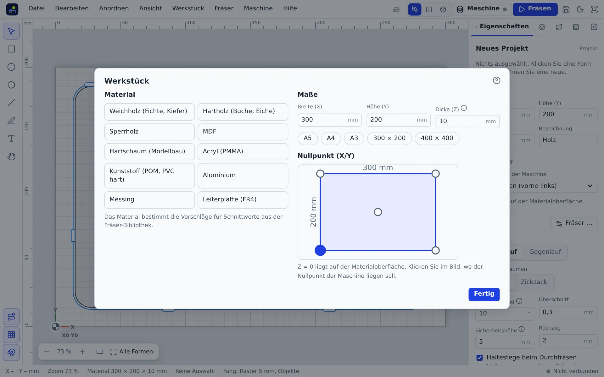
Material
Softwood, hardwood, plywood, MDF, foam, acrylic, plastic, aluminium, brass or PCB. The material decides which cutting data the bit library suggests.
Size
Width (X) and height (Y) in mm. Common sheet sizes are listed below to click. Work area uses the size of the machine you set up. If the material is larger than the machine can reach, the app warns you.
Thickness
The thickness (Z) is the most important value: Cut through depends on it (thickness plus overcut). Measure the real sheet with calipers at several points. A sheet sold as 6 mm plywood is often 5.6 mm or 6.3 mm. The carve wizard asks for the measured thickness again before the start.
Zero point
The zero point is where you place the machine before starting. All toolpaths refer to it. Click one of the four corners or the centre in the picture.
- Bottom left (default): convenient when the material sits against stops.
- Centre: handy for round parts or when you marked the centre.
Z = 0 is always on the material surface. How to set zero on the machine is explained in Machine control and Probing Z.
Large workpieces in sections
If the material is longer than the machine can travel, work on it in sections. Turn on Large workpieces in sections in the “Workpiece” window. The app suggests a section length that suits the machine's travel.
- Slide direction: forward (Y) for long boards, to the left (X) for wide ones.
- Length per section: at most the travel minus some room for the bit and the mark. The app warns you if a section is too long.
- Alignment marks: at the end of each section the app cuts two short grooves, 0.3 mm deep, at both edges. After sliding, they show where the next section begins.
The canvas shows the section borders as dashed lines. Toolpaths are split exactly at these borders, so the sections join seamlessly. Each section is a separate program, one per bit if you use several bits. The zero point is always at the front left of the current section.
How to proceed:
- Place the material against a straight fence running parallel to the slide direction and set the zero point at the front left.
- Cut the first section as usual with the carving assistant.
- Release the clamps, slide the material along the fence by exactly the section length and clamp it again. The zero point stays.
- In the X/Y zero step the carving assistant shows Go to mark. Lower the tool to just above the surface: it must sit centred over the groove. If it is off, adjust with the arrows and click Zero Y here (or Zero X here).
- Repeat until the last section.
With the rotary axis turned on there are no sections.
Several workpieces
A project can hold several workpieces, for example a birch board and an offcut of plywood next to it. Workpiece → Add another workpiece … or the Another workpiece button in the Workpiece window places a new one to the right of the others.
- At the top of the window pick the workpiece as a tab. Size, thickness and material apply only to the selected one.
- Position X/Y moves another workpiece on the canvas; its shapes move with it.
- A shape belongs to the workpiece that holds the centre of its outline. Just drag it across.
- Remove workpiece deletes only the workpiece, its shapes stay where they are.
Each workpiece is cut on its own, with its own programs and its own zero at the same corner as the first one. The job wizard shows which workpiece is next. When the next one comes up, clamp it and set the X/Y and Z zero again.
Several workpieces and sections cannot be combined.
Two sides (flip workpiece)
For parts that are machined on both sides, such as a cutting board with a juice groove on top and finger grips underneath, turn on Two sides in the “Workpiece” window (also under Workpiece → Two sides ▸).
- In the status bar at the bottom you switch between Top side and Bottom side. Drawing, selecting and milling always apply to the chosen side only; new shapes land on it.
- Draw the bottom side the way the workpiece lies on the machine after flipping: same zero point, text readable. The other side shows through mirrored and faintly dashed, so you can place matching features exactly.
- Flip sets how you turn the workpiece over: swap left and right (like a book page) or front and back. The dash-dotted flip axis runs through the middle.
- Dowel pins: the top side first mills two holes on the flip axis, through the workpiece into the spoilboard. Put pins in and set the flipped workpiece on them: it lies exactly as before. Diameter, distance from the edge and depth can be set; the holes are milled with the largest end mill of the project that is smaller than the hole.
All programs of the top side are milled first, then those of the bottom side. Before the first program of the bottom side, the milling assistant shows the steps: flip, set it on the pins (without pins, place it against the same stops and set the X/Y zero at the same corner) and probe Z again. The Milling tab, the 3D view and the preview show the chosen side; where pockets from both sides meet, the part is cut through.
Two sides, several workpieces, sections and the rotary axis exclude each other.
Clamps
Under Workpiece → Clamps … you enter what holds the workpiece down: clamps, screws and free keep-out zones, for example for a stop or a clip. The layout shows the workpiece with all toolpaths, and you drag each clamp into place. Set size and position exactly in the fields.
- Height above workpiece: top edge of the clamp above the top face. Up to this height (plus 1 mm clearance) the bit must not touch the outline.
- The check uses the bit radius and follows every move just as the program runs it: cuts, retracts between paths, moves at safe height and the return to the origin.
- If a toolpath hits a clamp, an error appears in the notices and the clamp turns red in the layout, on the canvas and in 3D. If only the safe height is too low, the notice gives the height needed; the field for it is right in the window.
On the canvas the clamps lie hatched under your drawing; in the 3D view they sit on the workpiece as solid bodies.
Millimetres or inches
Under Settings → Language, units and account → Units you choose millimetres or inches. The choice applies to every size field, text, the rulers, the position display and the jog steps. Projects, bits and G-code stay metric, so you can switch at any time.
You can also type the unit into any size field: “12mm”, “1/4 in”, “2"” or “3 cm” are converted for you. Controller values (such as $130) stay in millimetres, the way the controller stores them.